

Virtual null-modem cables vs virtual serial ports: creation and usage

Many users who assignment with Windows Mobile consecutive applications abutting by null-modem cable
(especially if those applications crave added than one consecutive ports pair) far added generally face the call to actualize basic consecutive ports. This functionality is added than all-important for GPS simulation programs. Generally, null modem allows to acceleration up development action during debugging and data-logging period.
Therefore there comes an affair of how to actualize basic com ports. In this commodity we will accede the affairs aimed at analytic this solution: Basic COM Anchorage Kit which creates basic consecutive ports and connects anniversary brace of them via basic null-modem cable. So, all abstracts accounting to one basic consecutive anchorage can be anon apprehend from the added one null modem, and carnality versa.
The way it works: the affairs creates basic consecutive ports and connects them via basic null-modem cable. So any applications can barter abstracts aloof like they do it via accouterments consecutive ports and absolute null-modem cables. In added words, it allows to affix two applications (like GPS simulation programs) over basic consecutive ports.
For example, appliance Basic COM Anchorage Kit, it is accessible to actualize pairs of basic consecutive ports (e.g. COM7 and COM8) and affix two applications to them. All abstracts that the aboriginal appliance writes to COM7 is apprehend from COM8 by the additional application, and carnality versa.
Virtual COM Anchorage Kit is able to:
- Affix consecutive applications via basic consecutive ports. All the abstracts accounting to one basic consecutive anchorage can be anon apprehend from the added one, and carnality versa.
- It is a accurate basic consecutive anchorage driver. Basic consecutive ports attending and assignment absolutely as absolute accouterments consecutive ports.
- It’s congenital up for altered platforms: Windows, Windows CE (ARM, MIPS, SH3, SH4 and x86).
Who can use Basic COM Anchorage Kit? The affairs is advantageous for users who assignment with Windows Mobile consecutive applications abutting by null-modem cable (especially if those applications crave added than one consecutive ports pair). For example, this band-aid can be acclimated for GPS simulation programs. It allows to acceleration up development action during debugging and data-logging period. One can alter your affairs (which uses consecutive port) by abutting it to addition affairs (e.g. consecutive accessory emulator).
Moreover if it is all-important to accommodate basic com anchorage functionality, the affairs supports it. So one can actualize and configure basic consecutive ports from your appliance directly.
General affairs features:
- Full accouterments consecutive ports appetite
- Basic consecutive ports attending and assignment like absolute accouterments ports
- Up to 9 basic COM anchorage pairs can be created
- Once created basic ports are applicable at anniversary arrangement startup (prior to user login)
- Basic advice is added fast and reliable than via absolute absent modem cable
- One bang enable/disable button for all basic consecutive ports
- Basic consecutive ports are controlled anon from one’s own appliance appliance Dynamic Link Library (OEM license).
http://www.articlesbase.com/software-articles
___________________________________________________________________________________
___________________________________________________________________________________
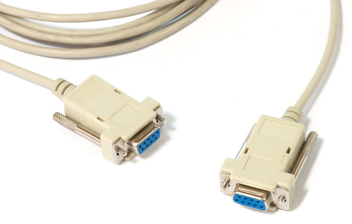
what's is a null modem?
A null modem cable allows you to affix your PC to addition adjacent PC or consecutive accessory application its modem protocol. A accepted use of absent modem cables is for ambience up "head-to-head" gaming amid two players at altered computers in the aforementioned room. (A absent modem cable is bound to 30 anxiety in length.)
The accepted null modem RS-232C consecutive communications interface defines a arresting agreement amid a Abstracts Terminal
Learn More
* LANs (Local Area Networks)
* Networking Resources
Equipment (DTE) - usually your PC - and a Abstracts Communications Equipment (DCE) - or your modem. The signals are transmitted on a set of lines, anniversary of which has a action in the "talk" that the DTE and DCE do aback and forth. One band anniversary way is for data; the added curve are for altered "statements" that one end of the advice sends to the other. For example, the DTE sends the DCE (usually a modem) a "Request to Send" arresting on the null modem RTS band and the DCE replies with a "Clear to Send" arresting on the CTS line. After a alternation of agnate exchanges, the DTE sends abstracts on the band adherent to transmitting abstracts (which for the DCE is a band for accepting abstracts from the DTE).
Since a modem or DCE is not absolutely bare to interconnect your PC with addition bounded consecutive device, the DTE interface can be acclimated by both your PC and the absorbed consecutive device. However, the null modem DTE interface is advised to assignment with a DCE device. What a null modem cable does is to accomplish the added end of the PC or device's DTE interface attending like a DCE interface.
A absent null modem cable is sometimes alleged a crossover cable.
___________________________________________________________________________________
The purpose of a null-modem cable is to permit two RS-232 "DTE" devices to communicate with each other without modems or other communication devices (i.e., "DCE"s) between them.
Virtual Null Modem is a utility, which purpose is to emulate one or more RS232 serial ports connected via virtual null-modem cable. Otherwise, you can create any number of pure virtual serial ports in your system (COM10, COM11, COM127 etc), that will be connected to each other via virtual null-modem cable.
Example of use of virtual null modem
You can create two virtual serial ports: COM10 and COM12 and connect two different applications to them. Everything, that application #1 will send to COM10 will be received by application #2 at COM12, and all that application #2 sends to COM12 will be received by application #1 at COM10.

__________________________________________________________________________________
A while back, I had a bunch of null-modem adapters made up. They have worked pretty well for a wide variety of applications, and a number of people have asked me about my bunch of null modem. I wrote up a description of them to send out to a couple of mailing lists, and that description has been sitting as an unlinked text file in my http directory for a year or so. Nevertheless, people keep finding it and I get the occasional question about it, so I figured I'd put it here as a web page to make it even easier.
I wish to emphasize that this is far from the only way to do this. This is just the way that I did it, and it's been shown to work for several people. Use it or ignore it as you wish. However, I do enjoy hearing from people who have built them.
NB: If anyone decides to sell these as a commercial product, please let me know and I'll include a link here to your company's website
Mike's Picture

NB: As noted by another reader, the order of the conductor colors in this image is not quite correct for most standard RJ45 adapters. The correct order for most adapters is blue, orange, black, red, green, yellow, brown, white. In this picture the conductors are swapped in pairs. Thanks to Gary Piccoli for bringing this to my attention.
Here is my response
The purpose of a null-modem cable is to permit two RS-232 "DTE" devices to communicate with each other without modems or other communication devices (i.e., "DCE"s) between them.
Virtual Null Modem is a utility, which purpose is to emulate one or more RS232 serial ports connected via virtual null-modem cable. Otherwise, you can create any number of pure virtual serial ports in your system (COM10, COM11, COM127 etc), that will be connected to each other via virtual null-modem cable.
What problems can be solved with Virtual Null Modem?
If you have two applications you want to connect to each other using serial ports you need a null modem. A null modem is bascially a cable to connect two serial ports to each other. Normally you need two computers or two physical ports on one computer to achive this. Using Virtual Null Modem software you can emulate the null modem and run the two applications on the same computer without any additional hardware.Example of use of virtual null modem
You can create two virtual serial ports: COM10 and COM12 and connect two different applications to them. Everything, that application #1 will send to COM10 will be received by application #2 at COM12, and all that application #2 sends to COM12 will be received by application #1 at COM10.
Getting started is easy. Virtual Null Modem is ready!
After installing Virtual Null Modem, start it from the "Start->Programs" group. The program will ask you about creating a new null modem device. You should click the "Yes" button and select two serial ports number in a dialog window. Click the "OK" button in the dialog window and click the "OK" button in the main window. Now, your virtual null modem serial ports are ready.
__________________________________________________________________________________
Null Modem Adapters
A while back, I had a bunch of null-modem adapters made up. They have worked pretty well for a wide variety of applications, and a number of people have asked me about my bunch of null modem. I wrote up a description of them to send out to a couple of mailing lists, and that description has been sitting as an unlinked text file in my http directory for a year or so. Nevertheless, people keep finding it and I get the occasional question about it, so I figured I'd put it here as a web page to make it even easier.
I wish to emphasize that this is far from the only way to do this. This is just the way that I did it, and it's been shown to work for several people. Use it or ignore it as you wish. However, I do enjoy hearing from people who have built them.
NB: If anyone decides to sell these as a commercial product, please let me know and I'll include a link here to your company's website
Requisition for Full-Handshaking Modular Serial Adapters for Use in the Simple Construction of RS-232 Null Modem Cables.
There are four custom modular serial adapters specified in this requisition. The intent is to have the ability to create full-handshake RS-232 null modem cables by using pairs of these adapters and four-pair straight-through Cat 5 patch cables (the cables will be procured seperately). As designed, any of the following combinations should work to provide the full-handshake null modem capability:Type1 <-> Type2 Type1 <-> Type4 Type3 <-> Type2 Type3 <-> Type4With the <-> representing a four-pair cat 5 straight-through patch cable terminated in RJ-45 modular plugs. In the following, "shell" means the metal shell of the D-sub contact housing null modem and the attachment to the shell must be soldered. All-plastic contact housings are not acceptable in this application.
Type 1
These modular adapters must have the following pinning:RJ45 DB25 (Female) 1 ---------- 1 -- shell 2 ---------- 2 3 ---------- 3 4 ---------- 4 5 ---------- 5 6 ---------- 6 -- 8 7 ---------- 7 8 ---------- 20The representation "6 ---------- 6 -- 8" is meant to indicate that pins 6 and 8 on the DB25 must be tied together and jointly connected to pin 6 of the RJ-45.
Type 2
Pinning for this adapter is as followsRJ45 DB25 (Female) 1 ---------- 1 -- shell 2 ---------- 3 3 ---------- 2 4 ---------- 5 5 ---------- 4 6 ---------- 20 7 ---------- 7 8 ---------- 6 -- 8The representation "8 ---------- 6 -- 8" is meant to indicate that pins 6 and 8 on the DB25 must be tied together and jointly connected to pin 8 of the RJ-45.
Type 3
These modular adapters must have the following pinning:RJ45 DB9 (Female) 1 ---------- shell 2 ---------- 3 3 ---------- 2 4 ---------- 7 5 ---------- 8 6 ---------- 6 -- 1 7 ---------- 5 8 ---------- 4The representation "6 ---------- 6 -- 1" is meant to indicate that pins 6 and 1 on the DB9 must be tied together and jointly connected to pin 6 of the RJ-45.
Type 4
These modular adapters must have the following pinning:RJ45 DB9 (Female) 1 ---------- shell 2 ---------- 2 3 ---------- 3 4 ---------- 8 5 ---------- 7 6 ---------- 4 7 ---------- 5 8 ---------- 6 -- 1The representation "8 ---------- 6 -- 1" is meant to indicate that pins 6 and 1 on the DB9 must be tied together and jointly connected to pin 8 of the RJ-45.
Notes
Following is an email about this that I sent to several mailing lists:From: Bob Drzyzgula To: PICLIST@MITVMA.MIT.EDU, linux-smp@vger.rutgers.edu, sparclinux@vger.rutgers.edu, beowulf@beowulf.gsfc.nasa.gov Cc: bob@drzyzgula.org Subject: FYI: Spec for serial null-modem modular adapters Reply-To: Bob Drzyzgula X-Editor: vim X-Operating-System: Redhat Linux 5.0 Hi. This is an FYI not meant for discussion (unless y'all want). I'd just been asked for about the fifth time for the specifications for some serial null-modem adapters that I had made up a few months ago, so I figured I'd write it up in a form that can be used as the starting point for a requisition or purchase order, and put it where people can find it. Rather than post it to all these lists, I've put it on my pitiful website at: http://www.eskimo.com/~bob/serial-spec.txt I'm just letting y'all know in case you might find it useful. I had 200 of each of the four types made up early this year for my office, and generally they've been solid and reliable; I've not come across a standard, basic null-modem application that these won't work for (they work well on a Sun ttya console) and they do generally work in many straight-through applications as well. We got ours made by NuData (part of fill-in-the-blank warehouse at http://www.warehouse.com), but pretty much any custom cable shop should be able to make them. In moderate volumes, they can come out about the same or less than pin-it-yourself parts. I suspect that others have come up with similar designs, some of which may have significant advantages over these. But these have worked well for us. BTW, the only commonly used asynch signal that isn't handled by these is RI, and both signal ground and frame ground are provided. TC and RC are not pinned, so these won't work for a synchronous line. Let me know if you find something wrong or have suggestions or problems with it.
Follow-up
As I mentioned, I occasionally get questions about this, and sometimes these do a good job of pointing out the shortcomings in my description. Here's the result of one such exchange, which may be helpful to others as well. Mike kindly consented to having his email and diagram included on this page.From: Mike Ingram [mailto:mike.ingram@(obscured)] Sent: Tuesday, June 06, 2000 3:35 PM To: bob@drzyzgula.org Subject: question about null modem adapters Hey Bob, I found your response to someone's question about null modem adapters (http://www.eskimo.com/~bob/serial-spec.txt) and I'm confused about something and wondering if you have a couple minutes to help me out. I tried to buy a DB9F > RJ45 Null Modem Adapter at the computer/electronics store, but they told me they don't sell them that way anymore, so I had to buy simply a "do-it-yourself" adapter, and they didn't have the specs for wiring them. That's where you came into the picture. I have figured out the numbering sequence of the wires coming from the rj45 side, and I have inserted them into the db9 female side, except for the remaining 2 wires which I'm confused about. I am using your "Type 3" guidelines and have inserted all the wires except for: orange (1) and green (6) (these are both coming FROM the rj45 side) You say to wire the DB9 1 and 6 wires together, but I must not have exactly what you're talking about because my DB9 side only has holes, and no wires. So I have OPEN holes in the DB9F side, holes 1, 6 and 9. And to reiterate, wires 1 and 6 from the rj45 side unused so far. So my stupid question is what do I do with the two remaining wires and 3 remaining holes? Attached is a better description of exactly what I'm talking about. Thanks so much for your time.
Mike's Picture
NB: As noted by another reader, the order of the conductor colors in this image is not quite correct for most standard RJ45 adapters. The correct order for most adapters is blue, orange, black, red, green, yellow, brown, white. In this picture the conductors are swapped in pairs. Thanks to Gary Piccoli for bringing this to my attention.
Here is my response
Mike,

Glad you found my description helpful. I'd almost forgotten
about it being out there.

Basically, the problem you're having is that you can't
make my design without either some solder or a crimp tool,
preferably both. The DIY adapters they sell have some
limitations when it comes to doing this kind of thing.

Re RJ45 pin 6:

If you have a crimp tool and some contacts, what you
do is take the line from RJ45 pin 6 and trim off the
contact, leaving as much of the wire as possible. Strip
about 1/8" of the insulation off the end of the remaining
wire. Then take another, maybe 1 to 1.5" wire and strip
1/8" of insulation off both ends. Crimp a contact on
one end of the short, free wire. Then take the free end
of the pin 6 wire and the second end of the short wire,
and crimp them both into the same contact.  Then put one
contact in hole 6 of the DB9 and the other contact in
hole 1. If you *don't* have a crimp tool and contacts,
what you will need to do is to sacrifice a second
adapter, by snipping one of the wires off at the RJ45
end. Then on the keeper adapter, snip the pin 6 wire
in half, and strip a bit from the three loose ends
you now have (two from the pin 6 wire -- one to the
contact and one to the RJ45 -- and one from the wire
you stole from the other adapter). Then you will want
to solder the three ends together and wrap them with
some electrical tape or heat-shrink tubing (if you use
heat shrink, remember to put it on the RJ45 end of the
wire *before* soldering and then slide it down over the
solder joint and shrink. I always forget to do that kind
of thing). Then, you can put the two contacts coming
from RJ45 pin 6 into holes 6 and 1 of the DB9. If you
have a bunch of these to do, I guess you'll be able to
get eight of these extra wires out of each sacrificial
connector.
null modem
Re RJ45 pin 1:

This pin carries the frame ground. What you need to do is
to snip off the contact (actually, I suppose, this could
be a source for an extra contact for the pin 6 thing,
although the remaining wire length could wind up being a
problem) and strip off some insulation. Then scratch or
sand off some of the plating on the metal shell of the
DB9 contact housing. Tin the end of the pin 1 wire and
solder it to the DB9 shell. It sounds crude, but that
is in fact the official way to do it -- even the ones I
had made professionally were done that way. A DB25 has an
extra pin for the frame ground (even though the shell is
still supposed to be connected to frame ground as well,
so my design connects both; thus it shouldn't matter if
your computer or whatever isn't properly grounded in both
places if you use my design), but on the DB9 there's not
enough pins and they use the shell as a contact.

When all is said and done, you could probably get away
with not doing this grounded-shell part at all and just
going ahead and using the RJ pin 1 wire for the DB pin 1-6
jumper. All the pin 1 to shell connection does is connect
the frame grounds of the two devices, and if both devices
are both properly grounded to the same reference, there
should be no potential difference between the two shells
anyway. Also, if you look at one of the devices you are
connecting and find that the metal shell of the male DB9 is
connected to nothing, like for example it was mounted in a
plastic case and there was no wire deliberately connecting
the shell to the device's ground, then the frame ground
isn't going to do anything for you anyway. I would expect
that a fairly small number of null-modem cables that are
ever built do this correctly.

As for DB9 pin 9, you don't need it. That is used for the
RI (ring indicator) signal from a modem to a computer, and
if you're building a null modem adapter, well....

Actually, this does point out a caution. In very many
cases, you can use a pair of even-type (2 and 2, 2 and 4 or
4 and 4) connectors or a pair of odd-type (1 and 1, 1 and
3 or 3 and 3) to form a straight-through cable. However,
you can't do this if you actually need the handshaking
signals to work correctly  -- mostly this works for your
basic RX/TX/SG cable -- and you can't do it to connect a
modem because RI isn't supported.

Actually, I think I might paste the text of this message
into that document, so let me know if something I said
doesn't make sense, or if you'd mind me including your
question.

Hope this helps,
null modem--Bob


